
use optimal network planning to build resilient networks
Recent events have highlighted the vulnerability of critical infrastructure by exploiting local points of attack, but with a global impact. A realistic resilience plan must identify these points of attack, quickly eliminate them and avoid them in the future. Today’s ‘fibre first, paths and services second’ design approach does not address this properly. It accumulates vulnerabilities in the late stages of network deployment as new services compete with those already in service. Network resilience to sabotage is not optimized. The attack angles of a potential saboteur with global impact remain hidden.
Only by analysing all levels of the network - under all constraints for a complete build - can you get a true understanding of how to protect networks against sabotage. This approach has been known for some time, but has been considered too difficult and complex to put into practice.
In this article, I show that with today’s hardware and recent advances in linear programming, end-2-end analysis becomes feasible. It paves the way for practical end-2-end planning and analysis of optimal resilient networks that can be applied to existing and newly planned networks.
In October 2022, the northern part of Deutsche Bahn’s (DB) GSM-R communications network was completely sabotaged by just two cuts in its fiber optic cables at two distant locations[1]. All trains stopped. Thousands of passengers were unable to reach their destinations. The depth of insight into DB’s fiber topology and the simplicity of the attack raise great concern. It drastically illustrates the importance and vulnerability of digital communications to critical infrastructure.
What can be done? The obvious is not possible: Just to increase the surveillance, isolation and protection of the entire infrastructure along the 34,000 km of German railroad tracks is far too difficult. A realistic plan must focus on the most critical elements. This requires a good understanding of the network’s angles of attack and points of failure. Only then can additional redundancy and protection measures achieve the goal of preventing future attackers from disrupting extended services with so little effort.
In other words, we need to ensure that our network design and changes to it provide security and robustness in the best and most efficient way possible.
Today’s design approach is not 100% helpful in this situation, as current network planning defines optimal paths, but not an optimal network, which leaves room for improvement.
Why is this a problem? What can be done better?
Communication networks are built on a hierarchical technology stack. Users or their applications define data transport by specifying source-to-destination forwarding 1, which is sent along paths that span multiple fiber links that carry packets from node to node. Clearly, the attack space is large, diverse, and heavily influenced by the flow capabilities predefined by the network design. It is difficult for the operations team to determine, where the fiber layout has opened up inherent vulnerabilities2.
Just to name a few examples where we might suffer:
Fiber redundancy layout may not be robust. Redundant paths (see sec. ¿sec:sec2?) run over different fibers, but are inadvertently bundled in the same cable or duct. Thus, destruction of one cable or channel segment will also cut the redundant path. Not good!
The timing may change too drastically after the redundancy switch over, so the real-time service cannot handle this change in characteristics and will not survive the event.
Congestion may occur after traffic is rerouted, which degrades the quality of service, which again does not ensure the service.
To complicate matters, modern networks use a wide range of technologies. (OTN,Ethernet/RSTP, MPLS-TP, IP, IP/MPLS, TSN, SDN, to name a few) to build the network topology.
Sure, they all define traffic in very different ways, but they all ultimately define, over what path and fiber, and with what characteristics, quality and protection, data will flow through the network. So the question, “Do we have a proper network design to support the specification?” remains a constant:

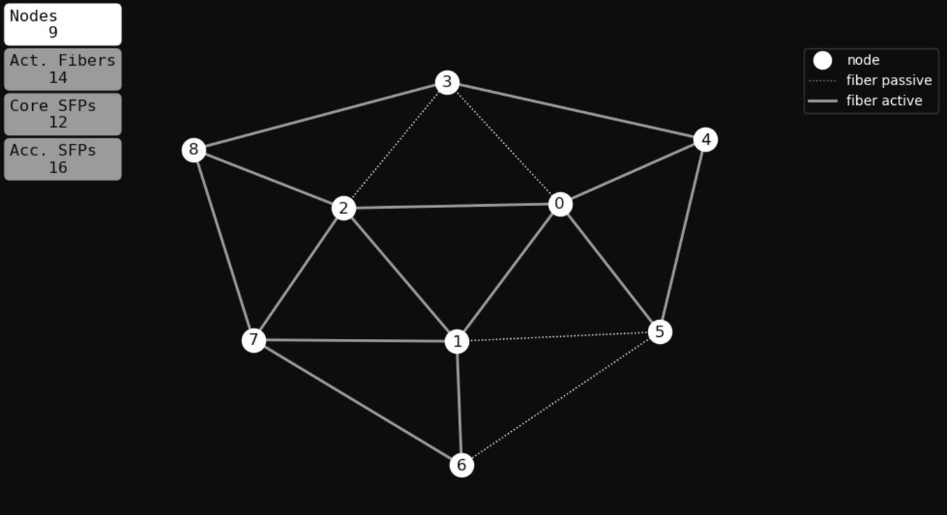
To give a practical example to shed light on this challenge please have a look into figure [fig. 1;]
We just consider a small core segment of 3 nodes 0, 1, 2, which are connected any to any, and which shall serve 6 access nodes 3, 4, 5, 6, 7 and 8. For connectivity there are 18 fiber links available.
To reflect real complexity, we consider multiple layers, but with only a few constraints to keep it digestible3. We first define rules in English to later translate them into mathematical formulas.
Since devices are limited in fiber ports (or SFPs), we have to choose which fiber can be served.
We consider an end-to-end communication service that spans multiple nodes: A real-time critical application where server needs to talk to a number of clients and vice versa without interruption:
Connecting two nodes in critical situations means relying on a path from source to destination that is kept alive under all circumstances, even if some fiber links 4 stop working. In order to protect against failure, an alternate path must be able to take over5.
To respect real-time, switch over has to be fast6 and protecting path needs to mirror working paths’ characteristics as close as possible.
Finally, we have cost as a competing requirement. Together with all the technical constraints we want to find a global optimum:
Avoid costs of optical fiber connection modules (small formfactor plugable SFP)
Rule5: Use as little fiber as possible. Core node SFPs are more expensive than aggregation SFPs, so avoid SFPs at [0,1,2].
But if invested, expensive optics must be used:
Rule6: Core hops are preferred over aggregation hops. Keep traffic on the inner ring [0,1,2].
In traditional design approaches, you start with an ad hoc fiber layout that satisfies the physical constraints. It is based on the assumption that this layout will provide a path routing that meets the specifications. Let’s see if this is justified.
With a little experience and intuition, we get three obvious starting points8.
In a first attempt, we work with two rings (see fig. 2;), a core ring [1,2,3] and an outer access ring [4,5,6,7,8] and connect them with three joints. In a sense, our design will consist of three rings9.
Rings are good for redundant design because they naturally provide two paths to each node. The use of SFPs at the core nodes is optimal. We only need 3 (see fig. 3;).
On the other hand, the long distance from 0 to 3 - neglecting the direct path - shows the disadvantage of this layout. Clearly, we will never get similar characteristics for the working and protecting paths. This gives us a first heuristic rule: pay attention to the size of your rings.
Since ring size is an issue, let’s make the rings smaller, which gives better length differences. But still for connection (0,3) a delta between working and protecting path of only 1 is not possible!
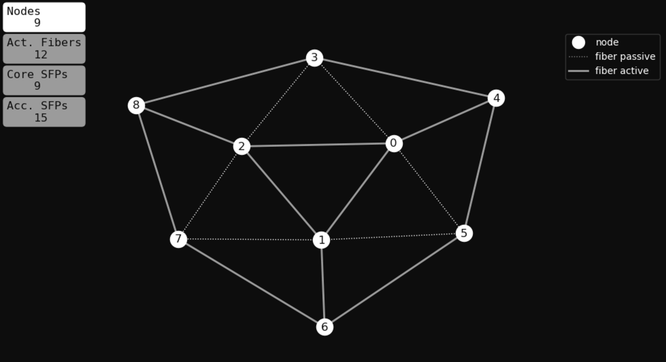
So let’s reduce the ring size even further. We arrive at the design shown in Figure[fig. 4;]. This should do it. Will it? We will see.

Once the fiber layout is established, network routing protocols, topology protocols, orchestrators or managers can do their work.
Whatever technology is used, they all look for the best path 10 from source to destination. The more advanced approaches are aware of protection needs, so they will optimize working and protecting paths together to ensure that they are disjunctive.
More ambitious algorithms will even try to optimize link capacities. They will create new paths along underutilized links to distribute bandwidth more evenly11. This is good for capacity constraints but creates a natural bias toward increasing complexity. More and more difficult compromises come later in the build.
In short, we can conclude: Current network planning defines optimal paths, but not an optimal network.
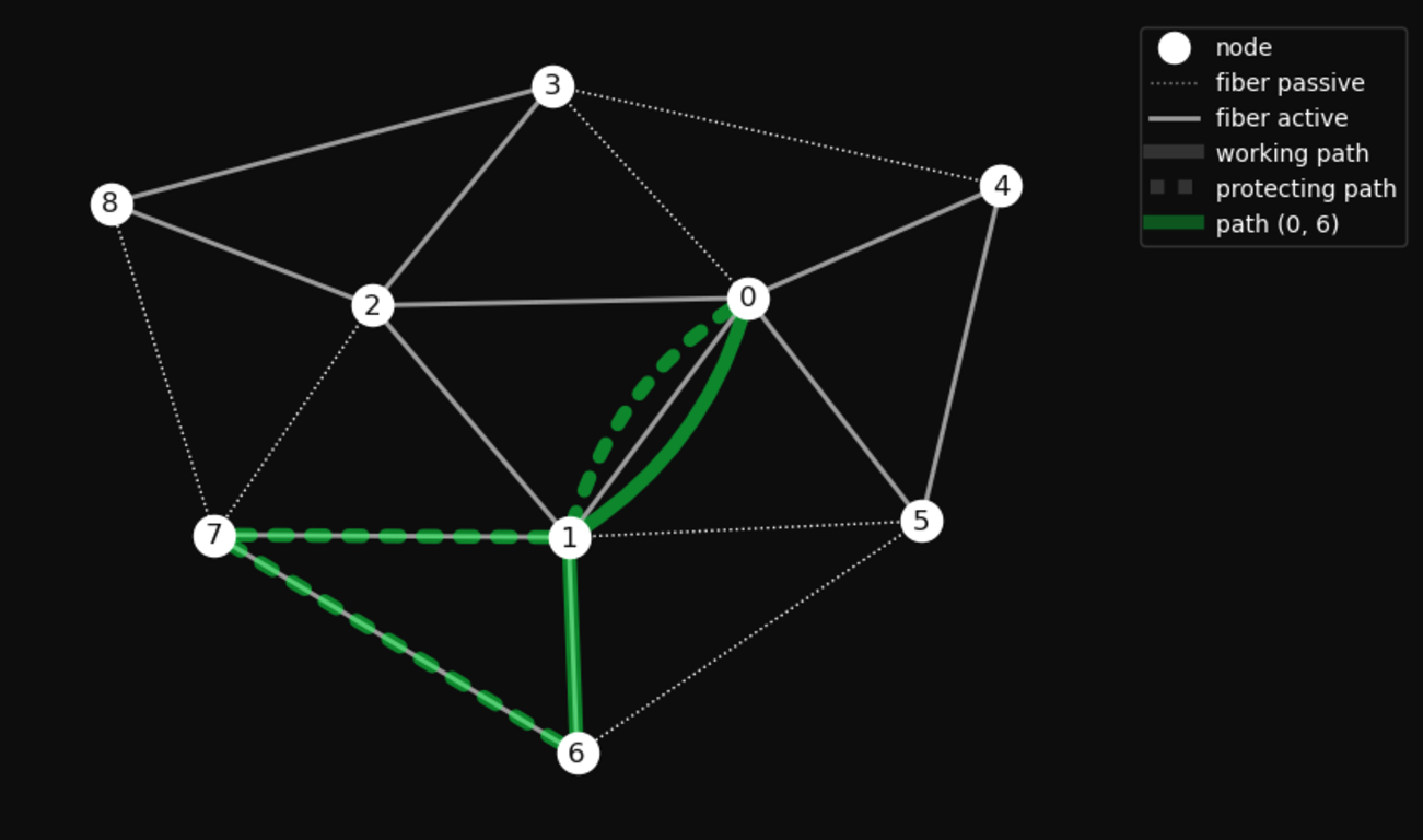
Let’s look at our example. When routing our ad hoc option shown in the figure \(\ref{fig:adhoc3}\), the paths for connection (0-4) and (0-5) come out fine. Not much of a delta. They are disjunct and well separated. Good job, router! But for connection (0-6) we cannot find a protected pair, that satisfies all the rules, either the difference in hops between the working and protected paths is too high or they are not separated. Not good!
As we have already seen, the other two options are even worse. Neither can make the difference in hop count equal to or less than 1.
As you can imagine. This can quickly become very frustrating and complex. Do we need core routers with 6 SFP ports? Or should we just try a different choice of active fiber? Should we go back to the drawing board and start over again, or should we invest in more hardware? It’s a quite an effort and there is no guarantee that it will work this time.
Is there a better way? Let’s see.
The industry has known for a long time that current approaches to network planning do not give us an optimal solution. We would have to optimize all levels and constraints at the same time. The method of choice is linear programming, a mathematical optimization scheme, that is well suited to this task, but has long been considered too difficult and too machine-intensive.
But times are changing. Methods and algorithms that have been dormant for many years due to lack of computing power and reluctance to dive into mathematics, are finally shining[2]. The current success in AI is a very prominent example.
With today’s laptops, our small problem can be solved in milliseconds. For realistic networks, such as the German mobile backhaul and FFTH network, optimal solutions were computed as early as ten years ago. These models were huge, but could be solved in minutes to hours. [3]
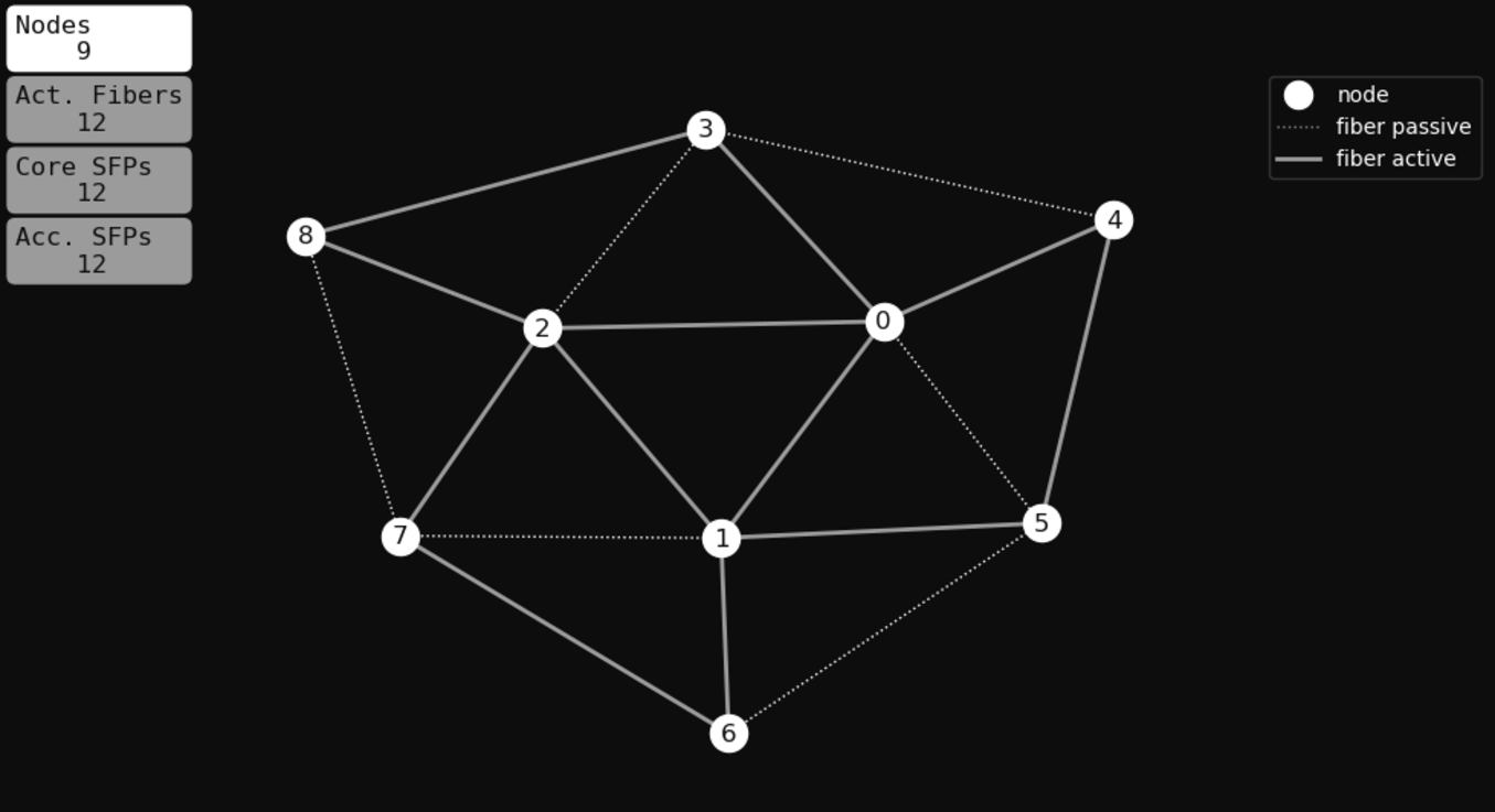
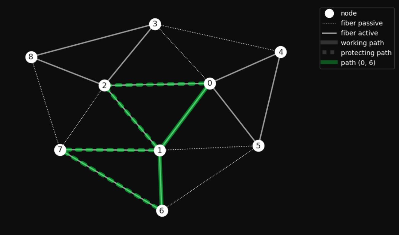
Transformed into standard form our problem can be solved by, for example with COIN|OR [4]. This gives us the solution for the network topology shown in fig. 5; and fig. 6;} 12
The optimal network is asymmetric and uses 2 more fibers than our ad hoc trials before. Nonetheless, the resource utilization is well within the limits.
You can convince yourself that all constraints are fulfilled at all levels. Paths are disjunct and number of hops differ by at most 1.
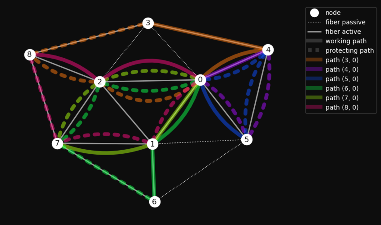
Have you seen this option? If not, don’t worry, the solution is not symmetric, so it’s difficult to find. In more realistic scenarios we would have many more parameters and no chance to find the optimum by hand anyway.
Not only when starting from scratch, but also for already deployed situations, this method helps. Formulating constraints in hard mathematical facts gives us an objective view of our status quo and its deviation from optimal. In my opinion, this is a proper and transparent way to identify angles of attack and ultimately plan defense.
Recent events have demonstrated the vulnerability of critical infrastructure. Any realistic protection plan needs to prioritize and identify low hanging fruit.
I hope I have shown how holistic network planning can help. How we can avoid easy points of attack. How to increase the robustness of the network design.
Doing this at all levels and under all constraints -instead of relying on an ad hoc initial assumption on fiber layout- has been too difficult in the past. Computational requirements and complexity of the tools had been too high.
I think that recent advances in usability, algorithms, and computing power will help to approach this in a new complete way. Currently, there is no plug-and-play software available. Formulating the model and defining the mathematical constraints requires a background in network engineering, requirements management, and mathematical optimization.
If you have experience in this area, have remarks/questions, or would like to know more about how to do this in larger scale with your network and team, please contact me. I am always open to interesting discussions and challenges.
https://wolfgangspahn.github.io/OptimalNetworkPlaning.pdf
In some sort, heavily depending on the technology used.↩︎
Maybe even better known to potential attackers!↩︎
For real networks there are much more rules to be considered.↩︎
In a more complete pictures we have to consider as well the nodes explictly, which we will fail to do in some of our ad hoc examples. You see it?↩︎
We name them working and protecting paths.↩︎
That’s the job of the node, the similarity has to be secured by the network!↩︎
When network load is low difference in hop count determines mainly the real-time behaviour. By applying different kinds of traffic shaping and priority methods, all protocols try that high prio traffic sees a nearly empty network, where frames don’t disturb each other. So the influence of number of hops asymmetry will stay, and needs to be managed↩︎
Be symmetrical, as humans think in symmetry!↩︎
the nodes 0,3,4,5 and 1 would represent such a subring. There are two others of the same type.↩︎
You may have trouble imagining that traffic in Ethernet/RSTP switched networks is routed along routed paths. Yes, there is no explicit path. We are on a switched network where each node does MAC-based forwarding. But think about it. Once the RSTP tree is set up and MAC learning is done, there is only one way to get from source to destination. That’s equivalent to our path. If a link fails, the RSTP topology will change to provide an alternate tree, which in turn provides a new path. This will create what we call a protection path. Of course, in the context of RSTP, paths are a rather verbose concept.↩︎
Since packet traffic varies, this can only be done statistically.↩︎
Link (2-3) as drawn red, as we want and any to any connected core. But it is not needed by any path in our example.↩︎